Proto V003 construction ideas
Posted by Taylor Bernard on September 24, 2013
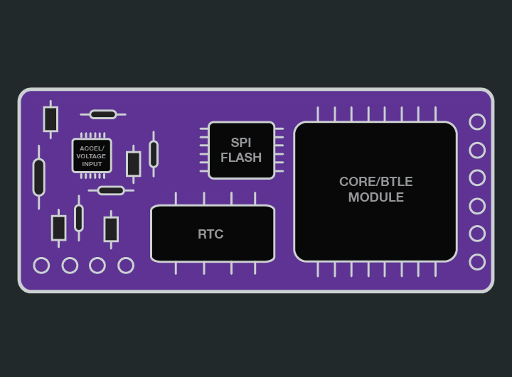
Here's my suspected layout. There has to be a coin cell battery, so on the back of the pcb there will be a Lipo battery (same size as pcb) and a coin cell holder for RTC.
next steps
- Find out how to program code onto a CORE/BTLE premade module. This will let us use existing hardware and not have to wait for rfDuino (which isnt a module and could fit on a custom pcb anyways).
- Find a smaller RTC chip that what exist on our DS1307 board from Adafruit, and make sure it can use libraries that are pre existing so we dont have to do custome .h files to #include.
- Find if can hire/source out someone that can help us with SPI Flash storage interface. Know we aren't going to be using MicroSD on final, so need to resource how hard it is to implement it now.
- Once parts in for V002 with high voltage killswitch line and tested working, check on other options for sensors. Possibly Acceleromter is best bet, since used by ICE dot system and they use the same ideas as us (BTLE, Lipo Battery, ect.)
Comments
Justin Bernard on September 25, 2013:
Justin Bernard on September 25, 2013:
Taylor Bernard on September 25, 2013:
heres the RFDigital module:
http://www.rfdigital.com/?targetpage=item&filterpn=RFD21733
you can see the diff between that and the RFDuino and this. The RFDuino has a USB input, header pins for jumper cables, stackability, ect. So they took a module, and made it modular and user friendly.
We need a straight module, that we can design a PCB around. See on the RFDigital module is has those half circle gold pads around the outside? those are solder contact points. On the pcb board there would be corresponding pads on the board, so the Module is placed flat on the PCB board and soldered to it. meshing the 2 together.
heres a great pic of the ICE dot i found:
as you can see, their size of design is limited by batter size as well. like ours will be.
--
you asked if we should reach out to someone and get them to make a module with BTLE and add on RTC for us. I think if we did that it would be major $$$, and may need re certification (FCC) of the BTLE Module. Its better to keep the module way it is and just add RTC on the main PCB board, there will be NO difference in size, connectivity, ect its just a few mm away.
Used Illus to do a visual mockup.
Confused on the last circuit i did. do you want it in depth all the way thru like a schematic of ALL the parts or just a layout diagram hooked in detail then going to a visual layout of the tinyduino circuits?
Justin Bernard on September 27, 2013:
"Confused on the last circuit i did. do you want it in depth all the way thru like a schematic of ALL the parts or just a layout diagram hooked in detail then going to a visual layout of the tinyduino circuits?"
we're dang close to me needing to file a provisional patent. pretty much as soon as we get it to work on bike im going to be hiring patent lawyer and starting the process. the first thing they are going to ask for is technical drawings. id like to have drawings of everything. v1/2/3, whatever we've done, document. if its too hard to do some elements, do as much as we can visualize and make notes on other pieces.